
Fonte (source): Consulting – Specifying Engineer
Por (By): Jerry Schuett, PE, and David Cunningham, Affiliated Engineers Inc.
Acesse aqui a matéria em sua origem.
Cogeneration systems—also known as combined heat and power (CHP) systems—generate both electricity and usable thermal energy. These systems typically are used on campuses that have high heat load requirements.
Learning objectives
- Understand the various forms of cogeneration systems.
- Learn to analyze the use of cogeneration systems.
- Anticipate regulatory trends toward growing and accelerating rates of cogeneration system adoptions.
Cogeneration systems, also known as combined heat and power (CHP) systems, generate both electricity and usable thermal energy. CHP systems provide a cost-effective method of reducing operating costs, increasing electrical reliability, and reducing greenhouse gases. A CHP system simultaneously converts mechanical work to electrical energy (in most cases) and produces useful heat. The efficiency of a CHP is approximately twice that of a standard utility electric-generating station, because the excess heat from the process is used beneficially in lieu of being dissipated to ambient air. These cogeneration systems, typically used on campuses with high heat load requirements (i.e., colleges, hospitals, and industrial campuses), offer efficiency, ease of system maintenance, and sustainable design opportunities.
CHP plant projects prioritize reliability, efficiency, sustainability, flexibility, and resiliency. CHP offers institutional, industrial, and commercial building owners a well-established means of increasing energy efficiency, decreasing risk of power outages (redundancy through islanding capability), reducing energy-related costs, and reducing greenhouse gas and air-pollutant emissions. The technologies that comprise U.S. capacity broadly align with applications determined by such characteristics as size, efficiency, capital and O&M costs, start-up time, availability, durability, system complexity, and emissions control. Fluency in the details of CHP systems and their performance is the starting point for effective application. While CHP has been around for more than a century, part of its renewed relevance today lies in its role as a vital part of energy projects seeking cleaner, greener energy.
CHP uses various fuel sources to simultaneously generate electricity and thermal energy, recovering heat that is otherwise exhausted from the power generation process. By capturing and using waste heat effectively, CHP uses less fuel than separate heat and power systems to produce the same amount of energy. Because CHP systems are located at or near points of use, transmission and distribution losses that would otherwise occur between a power plant and the user are essentially eliminated. As a form of distributed generation, CHP can provide high-quality electricity and thermal energy to a location regardless of power grid status, at the same time reducing grid congestion and deferring the need for new central generating plants.
Increasing interest in CHP is being driven by global energy demand, price volatility, and climate change concerns. Compared to the 45% efficiency typical of traditional separate production of heat and power, CHP systems can operate at efficiency levels exceeding 70%. Current CHP generating capacity in the U.S. is approximately 85 GW, or 9% of the U.S. total. This existing CHP capacity avoids 1.9 quads of fuel consumption (equivalent to 68.4 million tons of coal) and 248 million metric tons of carbon dioxide (CO2) emissions (equivalent to 45 million automobiles) per year. A recent U.S. Dept. of Energy report prepared by Oak Ridge National Laboratory, Oak Ridge, Tenn., estimated that raising CHP capacity to 20% of the total U.S. electrical production capacity required by 2030, or 241 GW, would avoid 5.3 quads and 848 million metric tons of CO2 (equivalent to 154 million automobiles). Government regulations encouraging CHP applications in Denmark, Finland, and the Netherlands have resulted in percentage capacities greatly exceeding this level in those countries. Recognizing the importance of CHP on a national scale, President Obama signed an executive order in 2012 establishing a national goal of adding 40 GW of new combined heat and power capacity by 2020.
CHP system types
CHP system types are identified by the prime-mover technology, which is configured with a generator, heat recovery, and electrical interconnections. These system types include back-pressure steam turbines, gas turbines, and reciprocating engines.
Back-pressure steam turbines: Back-pressure steam turbines have a variety of designs and can be matched with multifuel boilers, industrial waste heat, and gas turbine waste heat. This is a typical application: Steam is generated at a higher pressure than necessary for the loads/process and can be run though a back-pressure turbine to generate electricity in an extremely cost-effective manner.
Gas turbines: Gas turbines (otherwise known as combustion turbines, or CTs), derived from jet aircraft technology, provide more than 60% of U.S. CHP capacity. Gas turbines create high-temperature exhaust heat that is well-suited to high-pressure steam production required by process industries.
Reciprocating engines: Reciprocating engines represent less than 5% of U.S. CHP capacity, but total more than half of the CHP systems in place. A low-cost technology that has remained current through efficiency and emissions improvement, reciprocating engines produce exhaust heat ideal for hot water production and generally have a higher electrical energy-to-thermal energy output than a standard CT.
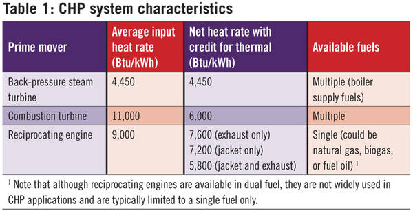
Table 1 was developed based on average input energy requirements and thermal output from various manufacturers, using an output range of 2,000 to 5,000 kW. The table lists the general characteristics of the aforementioned CHP system types, and is based on the higher heating value (HHV) of the fuel.
CHP characteristics: CTs, reciprocating engines
Heat recovery associated with a combustion-turbine CHP consists of a heat recovery steam generator (HRSG) downstream of the CT, which reduces the flue gas temperature from approximately 1,000 F to 350. An economizer can be located downstream of the HRSG to increase heat recovery and reduce the flue gas temperatures to approximately 250 F for noncondensing, and even lower for condensing economizers. The HRSG can produce a variety of steam pressures and temperatures, and can also produce water for heating. A duct burner can be installed between the CT and the HRSG to increase heat output for recovery by up to a factor of approximately 4, as necessary. The efficiency of a duct burner is approximately 90% based on using HHV fuel, because all of the required combustion air is provided by the CT exhaust at an elevated temperature.
The heat recovery from a reciprocating-engine CHP system comes from two separate systems. The heat recovery from the engine exhaust is similar to the heat recovery associated with a CT application. This source recovers approximately 15% of the heat input for an engine CHP application. A second source of heat recovery from a reciprocating engine is the jacket water, similar to an automobile radiator. This source produces approximately 20% of recoverable heat. Some engines also have a smaller component of heat recovery available from air coolers or oil coolers. This engine waste heat is mainly in the form of heating water due to the lower temperatures associated with it. The range of net heat rates vary depending on whether the jacket-water heat is recovered as well as the engine-exhaust heat.
